Content
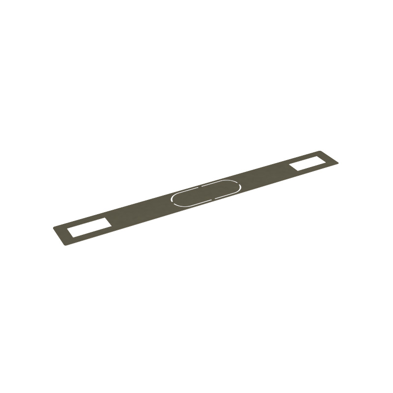
A prismatic cell cover is the structural cap or lid that seals the top opening of a prismatic lithium battery cell. Once the electrode stack and electrolyte are placed inside the rectangular metal can, the cell cover is welded or crimped onto the top to create a hermetically sealed enclosure. It is not simply a cosmetic lid — the prismatic cell cover is a precision-engineered component that performs several critical mechanical, electrical, and safety functions simultaneously.
The cover houses or integrates several key elements: the positive and negative terminal posts through which current enters and exits the cell, the electrolyte injection port used during manufacturing to fill the cell with liquid electrolyte before final sealing, and the pressure relief vent or explosion-proof valve that safely releases internal gas if the cell is overcharged or experiences thermal runaway. In many designs, the cell cover also incorporates a ceramic or polymer insulating seal around each terminal post to prevent short-circuiting between the terminal and the metal housing, which is typically at a different potential.
Prismatic battery cell covers are used across a broad range of applications — from large-format LiFePO4 (lithium iron phosphate) cells in electric vehicles (EVs), energy storage systems (ESS), and electric buses, down to smaller prismatic lithium-ion cells in laptops, power tools, and medical devices. The specific design, dimensions, material, and feature set of the cover vary significantly depending on the cell's capacity, chemistry, and intended use environment.
A prismatic cell end cover is not a single flat piece of metal. It is a sub-assembly that integrates multiple components, each serving a specific function within the overall cell design. Understanding what's built into the cover helps you evaluate quality and compatibility when sourcing replacements or designing battery packs.
The positive and negative terminal posts are the two conductive pillars that protrude through the cell cover. In most large-format prismatic LiFePO4 cells, the positive terminal is made from aluminum and the negative terminal from copper, chosen to match the current collector materials inside the cell and minimize contact resistance. Each terminal post passes through a precisely machined hole in the cover and is isolated from the cover body by a tight-fitting ceramic or polymer insulating seal — typically made from polypropylene (PP), polyphenylene sulfide (PPS), or a ceramic composite. This seal must maintain a hermetic, leak-free barrier against electrolyte vapor while withstanding vibration, thermal cycling, and the mechanical stress of torquing bus bar bolts onto the terminal during pack assembly.
During manufacturing, the cell is assembled dry (without electrolyte), the cover is welded on, and then electrolyte is injected through a small filling port in the cover. After filling and formation cycling, this port is permanently sealed with a steel or aluminum ball that is laser-welded or press-fitted into place. On a finished cell, the sealed injection port is visible as a small raised circle or plug on the cover surface. In field-returned or damaged cells, an improperly sealed injection port can be a source of electrolyte leakage.
The safety vent is one of the most important features on a prismatic battery cell cover. It is a precisely scored or thinned area of metal — often a cross-shaped or circular groove — engineered to rupture at a specific internal pressure threshold, typically in the range of 0.6 to 1.2 MPa depending on the cell design. When internal gas pressure from electrolyte decomposition or thermal runaway reaches this threshold, the vent opens in a controlled manner, releasing gas and preventing the cell from rupturing explosively. The vent is designed as a one-time passive safety device — once activated, the cell is considered failed and must be removed from service. A cover with a damaged, corroded, or previously activated vent is a serious safety hazard and must be replaced immediately.
Some prismatic cell covers — particularly those used in consumer electronics and certain automotive cells — integrate a current interrupt device (CID) directly beneath the cover. The CID is a mechanical switch that disconnects the internal electrode connection from the terminal post if internal pressure rises above a lower threshold, before the safety vent opens. This provides an earlier, non-destructive level of overcurrent and overcharge protection. Not all prismatic cell designs include a CID, as larger-format cells typically rely on the battery management system (BMS) for primary protection and the vent as the last-resort mechanical safety device.
The material selection for a lithium prismatic cell cover involves careful trade-offs between weight, corrosion resistance, thermal conductivity, weldability, and cost. The wrong material choice can lead to electrolyte corrosion of the cover, poor laser weld quality, or excessive weight in weight-sensitive EV applications.
| Material | Common Use | Key Advantage | Key Limitation |
| Aluminum Alloy (1060, 3003) | EV, ESS, LiFePO4 cells | Lightweight, excellent laser weldability, corrosion resistant | Lower strength than steel at same thickness |
| Stainless Steel (SUS304) | High-pressure cells, specialty applications | High strength, excellent chemical resistance | Heavier, higher cost, harder to weld |
| Cold-Rolled Steel (SPCC) | Lower-cost consumer cells | Low cost, good formability | Susceptible to corrosion without coating |
| Nickel-Plated Steel | Consumer electronics cells | Improved corrosion resistance over bare steel | Plating can degrade under harsh conditions |
For modern large-format prismatic LiFePO4 cells used in EV battery packs, aluminum alloy covers in the 1.0–1.5mm thickness range are the industry standard. The aluminum is compatible with the non-aqueous electrolyte solvents used in lithium cells, provides excellent laser weld joints with the aluminum cell can, and keeps the overall cell weight as low as possible — an important factor when thousands of cells are assembled into a single vehicle battery pack.
The manufacturing of a prismatic battery cell cover involves several precision processes, and the sealing method used to attach the cover to the cell body is one of the most critical steps in the entire cell assembly process. Any defect in the seal — even a pinhole — will lead to electrolyte leakage, moisture ingress, and premature cell failure.
The cover plate itself is produced by precision stamping from sheet aluminum or steel. The terminal post holes, vent groove, and injection port hole are typically formed in the same stamping die or in secondary machining operations. Tight dimensional tolerances are critical — the cover must fit precisely into the cell can opening to ensure a consistent weld joint. For high-volume cell production, covers are produced in automated stamping lines capable of millions of pieces per month, with 100% dimensional inspection using vision systems and laser measurement equipment.
Terminal posts are assembled into the cover with their insulating seals in a sub-assembly process. The seal material is compression-molded around the terminal post and pressed into the cover hole, creating a mechanical interference fit that provides both the electrical isolation and the hermetic seal. The assembly is then subjected to a helium leak test to verify the seal integrity before the cover moves to the next production stage. Seal failure rates are held to parts-per-million levels in quality cell manufacturing, as a leaking terminal seal is not repairable once the cell is assembled.
Once the cell interior is assembled and the cover is placed onto the can, the joint between the cover edge and the can wall is sealed by continuous laser welding. Modern prismatic cell production lines use high-power fiber lasers that produce a consistent, narrow weld bead around the entire perimeter of the cover in a matter of seconds. The laser parameters — power, speed, focal position, and shielding gas flow — are tightly controlled and monitored in real time. After welding, every cell undergoes a helium leak test where the cell is placed in a test chamber and any helium escaping through a weld defect is detected by a mass spectrometer. Cells that fail the leak test are scrapped immediately.
One of the most practical challenges when sourcing replacement prismatic cell covers — or designing a new battery pack — is dimensional compatibility. Unlike cylindrical cells, which have internationally standardized sizes (18650, 21700, 26650, etc.), prismatic cells do not follow a universal standard. Cell dimensions vary significantly between manufacturers and even between product generations from the same manufacturer.
When specifying or sourcing a prismatic battery cell cover, the following dimensions must be precisely matched:
Whether you're a battery pack designer sourcing covers for small-volume custom cell production, a repair technician replacing damaged components, or a battery manufacturer evaluating new suppliers, quality evaluation of prismatic cell covers requires checking several specific attributes beyond just price and dimensional fit.
Reputable suppliers provide material certificates (mill certificates) for the aluminum or steel used in their covers, confirming alloy grade, mechanical properties, and chemical composition. For applications subject to automotive quality standards (IATF 16949) or safety regulations, full material traceability from raw material to finished part is a basic requirement. Covers made from unverified or recycled metal of unknown composition can have inconsistent hardness, poor weldability, and unpredictable vent activation behavior.
Ask suppliers about their incoming and outgoing inspection protocols for seal integrity. Quality covers should have documented leak test results, ideally performed using helium mass spectrometry or equivalent. The acceptable leak rate for a properly sealed prismatic cell cover terminal insulator is typically less than 1×10⁻⁷ Pa·m³/s. Suppliers who cannot provide test data or who rely only on visual inspection should be treated with caution.
The vent groove scoring on the cover must be machined to a consistent depth to ensure the vent activates reliably within the specified pressure range. Covers with variable vent groove depth — caused by worn tooling or poor process control — may vent too early (reducing cell performance under normal swelling) or fail to vent at the correct pressure during a genuine fault event. Request vent activation pressure test data from the supplier, showing the distribution of activation pressures across a sample lot.
The mating surface between the cover edge and the cell can must be clean, flat, and free from burrs, oxidation, or contamination. Oil residue from stamping operations must be fully cleaned off before laser welding, as even small amounts of contamination cause weld porosity and weak joints. Inspect covers under magnification for stamping burrs at the edges, and confirm with the supplier that their post-stamping cleaning process is validated for laser welding compatibility.
When a prismatic lithium cell develops problems, the cover is often where the first visible signs appear. Recognizing cover failure modes can help diagnose the root cause of a cell or pack problem more accurately.
 Applet
Call Center:
![]() Tel:+86-0512-63263955
Tel:+86-0512-63263955
![]() Email :[email protected]
Email :[email protected]
Copyright © Goode EIS (Suzhou) Corp LTD
 Insulating Composite Materials and Parts for Clean Energy Industry
 cn
cn English